|
CNGS Target Station T40 - assembly in
the laboratory
The CNGS
target station is the "heart" of the facility. The target
consists of thirteen 10 cm long graphite rods, 5 and 4 mm in diameter. The
first 9 rods are interspaced by 9 cm of air, the last 4 rods are installed
without any air space in between them. The rods are installed in a target
unit (cf. the
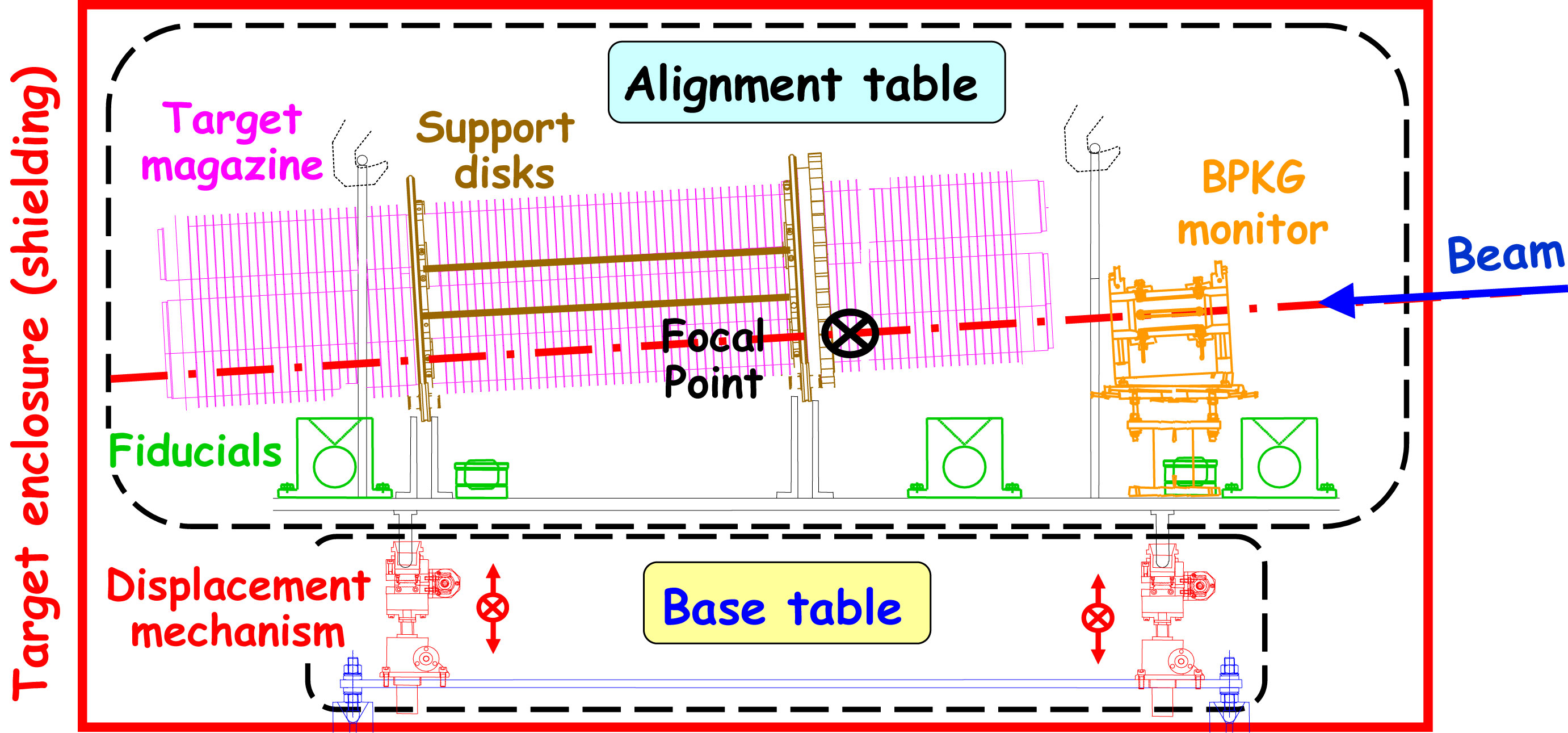
schematic drawing). The CNGS target station contains 5 units
(one active and 4 spares) in a rotatable target magazine. Together with a
BPKG position monitor, the target magazine is installed on the "alignment
table". The four jacks to adjust the position of this table are fixed on
the so-called "base table" (cf. the
schematic drawing of the assembly) . The
entire assembly is installed inside an array of massive iron shielding
blocks.

Pictures shown below illustrate
progress on the construction of elements and document the complete
assembly of the target station in a laboratory at CERN. All elements of
the target station will be transported to the target chamber for
installation - this operation is scheduled for September 2005. (Pictures:
Damien Grenier, Luca Bruno, CERN photo)
Target units: assembly and tests
Target
magazine and BPKG
Base
table
Shielding/assembly
|
|
|
|
|
Schematic drawings |
|
|
|
|
 |
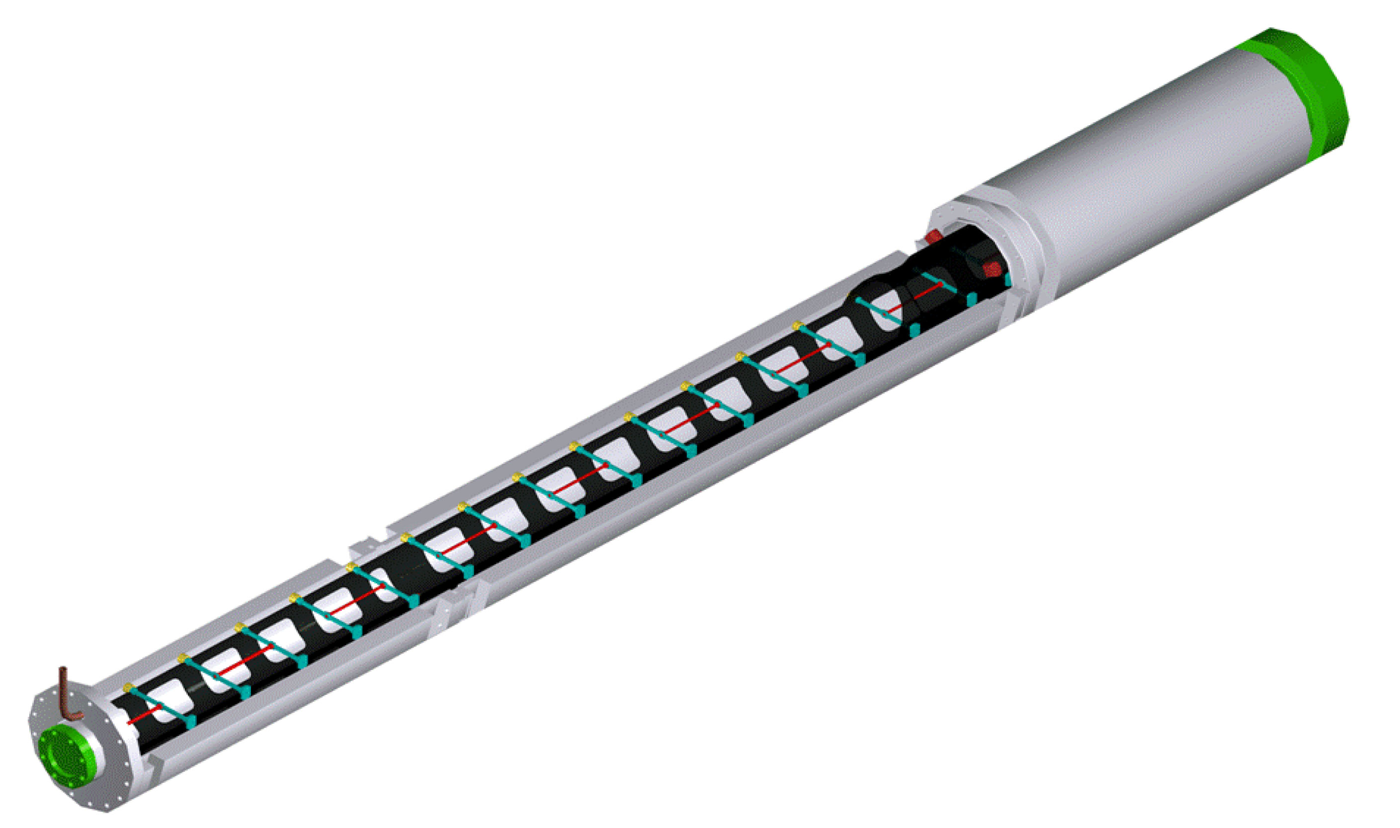
Target unit, schematic view
(cut open). Graphite rods are indicated in red, C-C supports for the
rods in blue. The C-C tube to hold the supports and allow alignment of the
rods is shown in black. The outer alu tube seals the 0.5 atm Helium volume
- upstream and downstream windows are of Beryllium. |
|
|
|
 |
Target
magazine (rotating "revolver"), schematic side view. (Five target units
form a target magazine: the lowest unit is in the beam, the others are
spares). |
|
|
|
|
Photos of target
unit assembly and tests |
|
|
|
|
 |
"Beam
eye" view of the prototype target, 15 December 2004 |
|
|
|
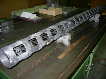 |
Prototype C-C tube with targets aligned in it, 15 December 2004 |
|
|
|
 |
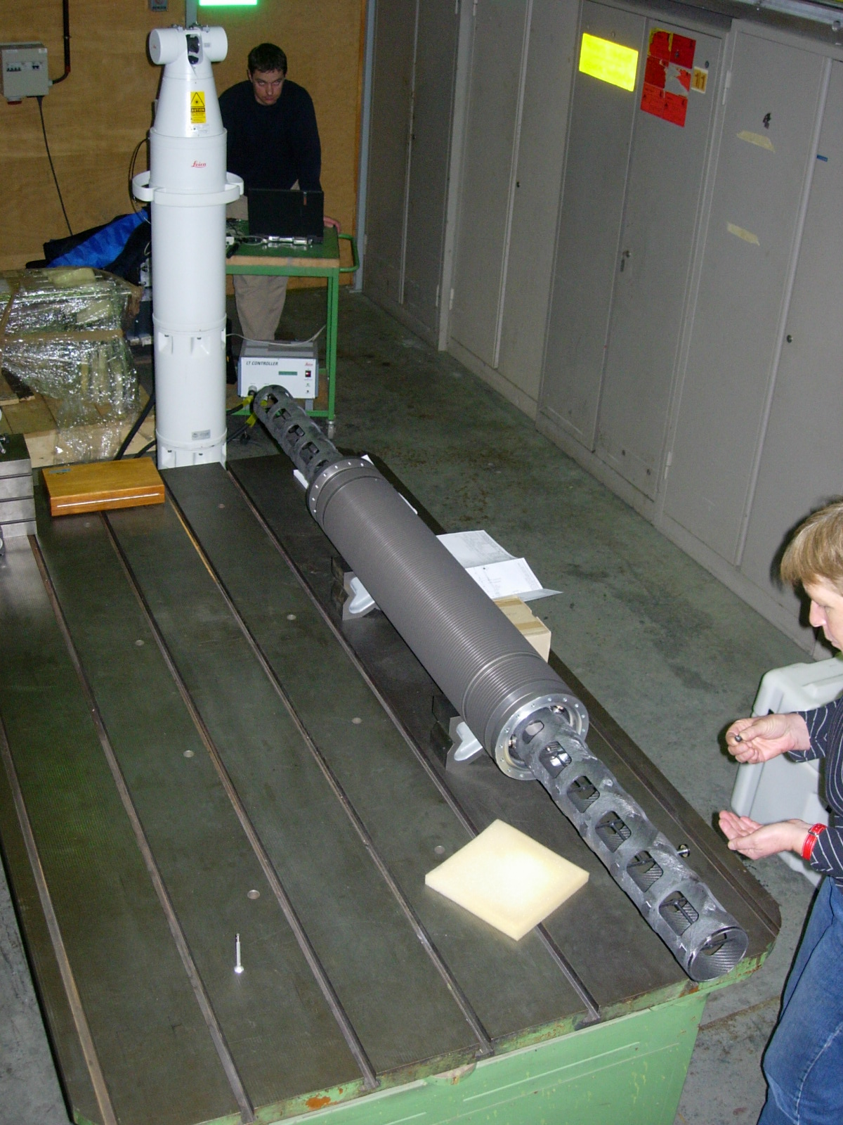
Alignment of targets inside the C-C tube, using the laser tracker,
15 December 2004 |
|
|
|
 |
Detail
of prototype target unit (open) - C-C tube fixed inside Alu tube, 17
December 2004 |
|
|
|
 |
Alignment of C-C tube inside Alu tube, using the laser tracker, 25 January
2005 |
|
|
|
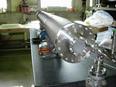 |
Prototype target unit on leak test stand, 18 February 2005 |
|
|
|
 |
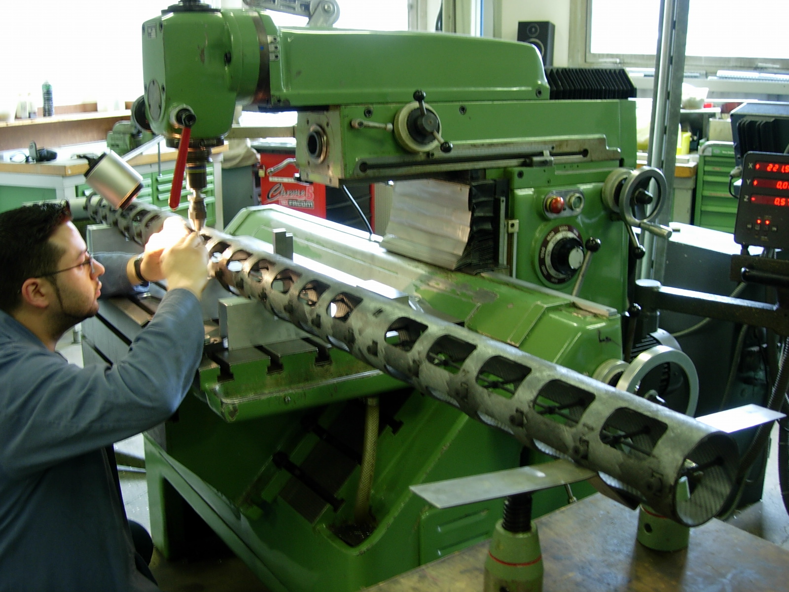
"Goupillage"
of target holders, 29 March 2005 |
|
|
|
 |
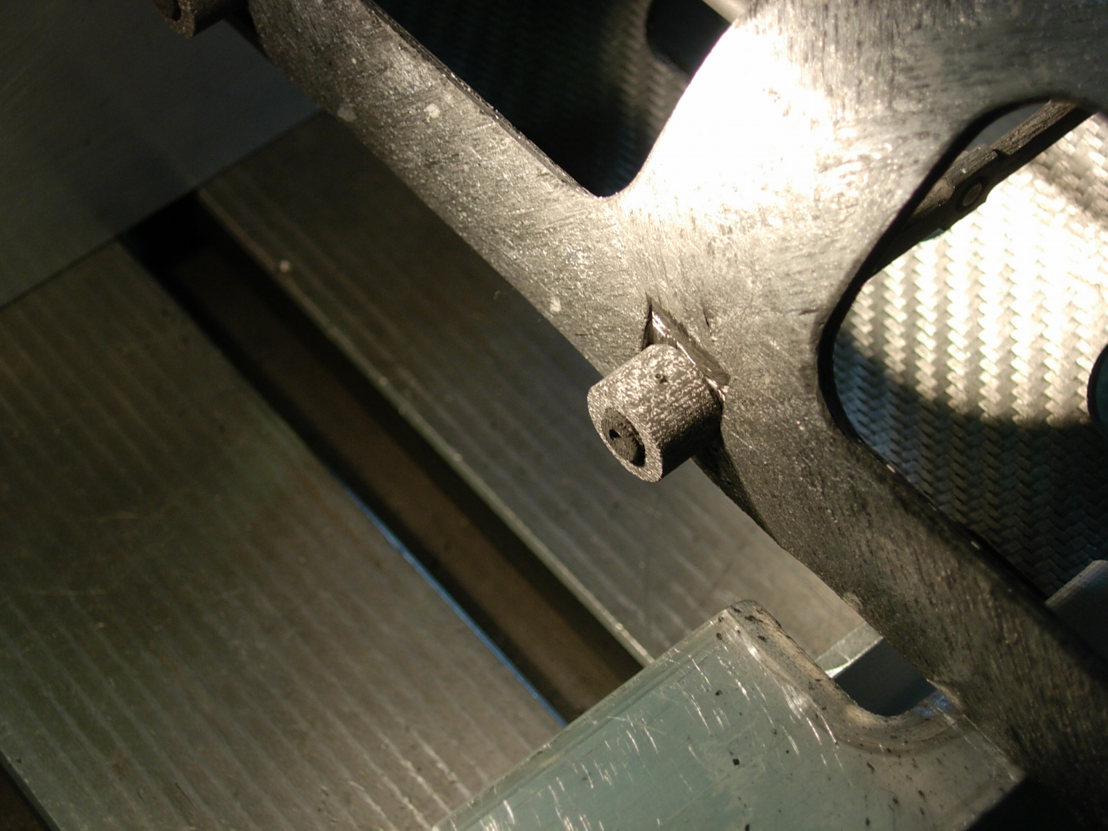
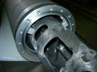
Detail of a target holder on
C-C tube, 29 March 2005 |
|
|
|
 |
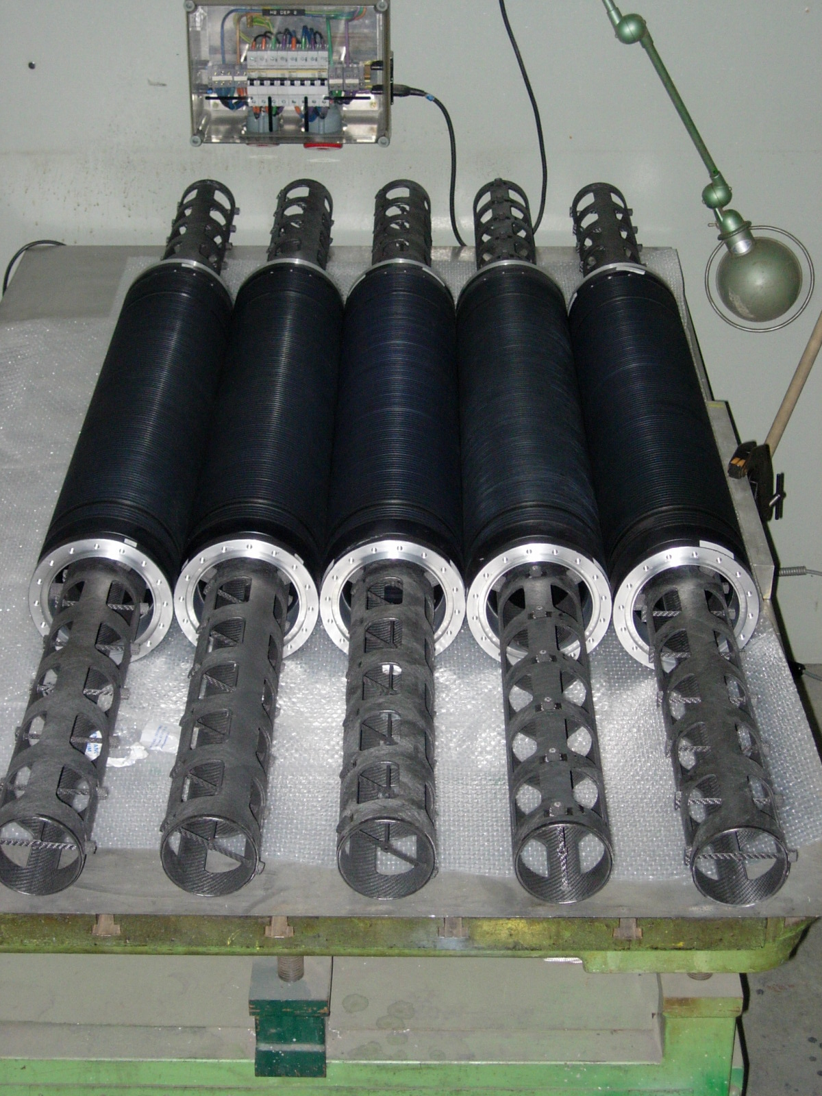
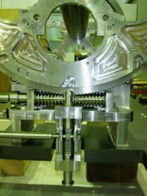
5 target
units, aligned, 7 April 2005 |
|
|
|
 |
Assembly
of C-C tube in Alu tube, 23 May 2005 |
|
|
|
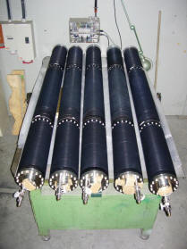 |
5 target
units, completed and helium leak tested, 30 May 2005 |
|
|
|
|
Photos of the target
magazine and BPKG monitor |
|
|
|
|
 |
Empty
target magazine, 27 May 2005 |
|
|
|
 |
Detail
of target magazine with indexing finger, 27 May 2005 |
|
|
|
 |
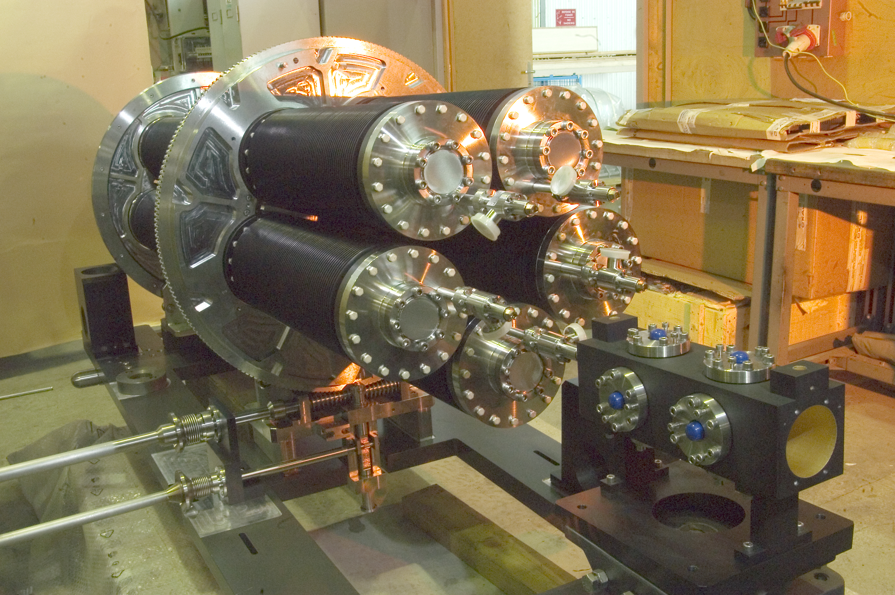
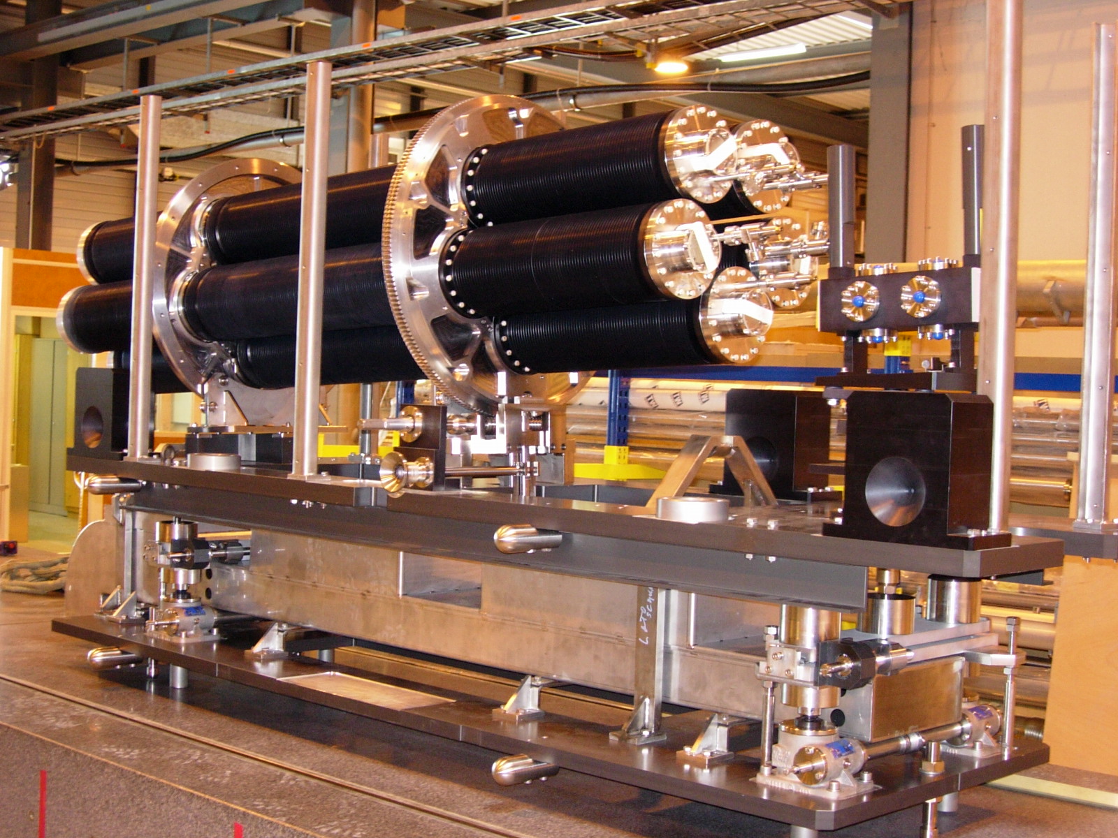
Completed target magazine, 1 July 2005 (in the foreground, the BPKG beam
position monitor) |
|
|
|
 |
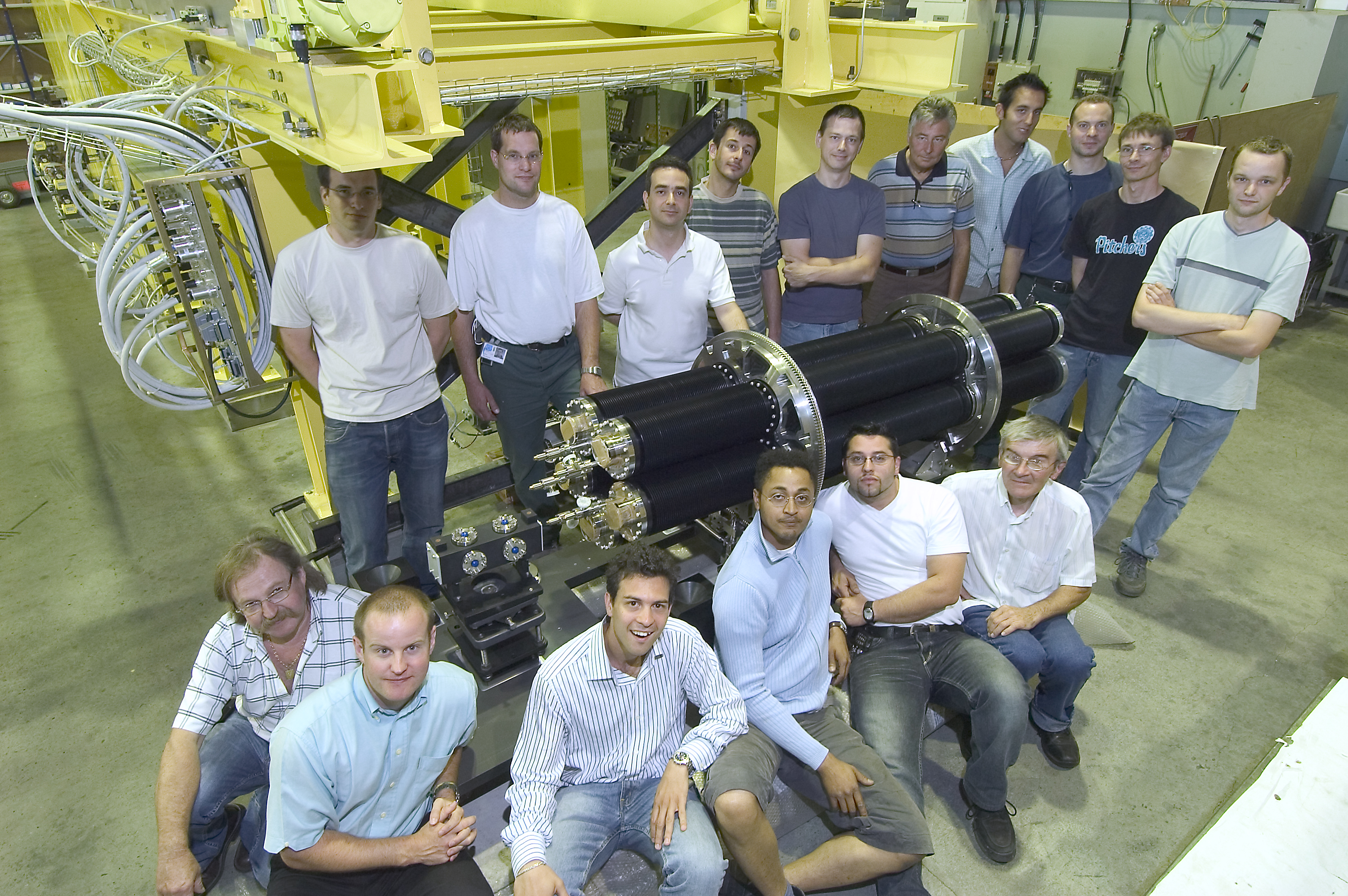
The
target team with the completed target magazine (1 July 2005). Not present
for the photo were J.F. Arbogast, R. Bonthond, P. Bourquin, M. Dupont, R.
Hanni, A. Lavenu, G. Patti, S. Sgobba, P. Sievers and J.K. Wickstrom |
|
|
|
 |
Testing
the target magazine rotation and indexing, 11 July 2005 |
|
|
|
 |
Assembly
and alignment of base table plus alignment table (with target magazine and
BPKG monitor), 3 August 2005 |
|
|
|
|
Photos of the base table |
|
|
|
|
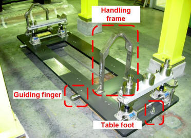 |
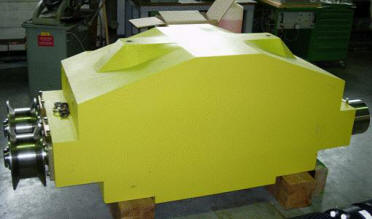
Base table
completed, 28 April 2005 |
|
|
|
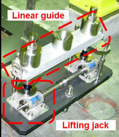 |
Detail
of base table |
|
|
|
 |
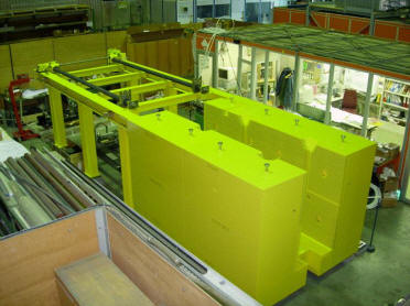
Base table
installed inside target shielding, 7 June 2005 |
|
|
|
|
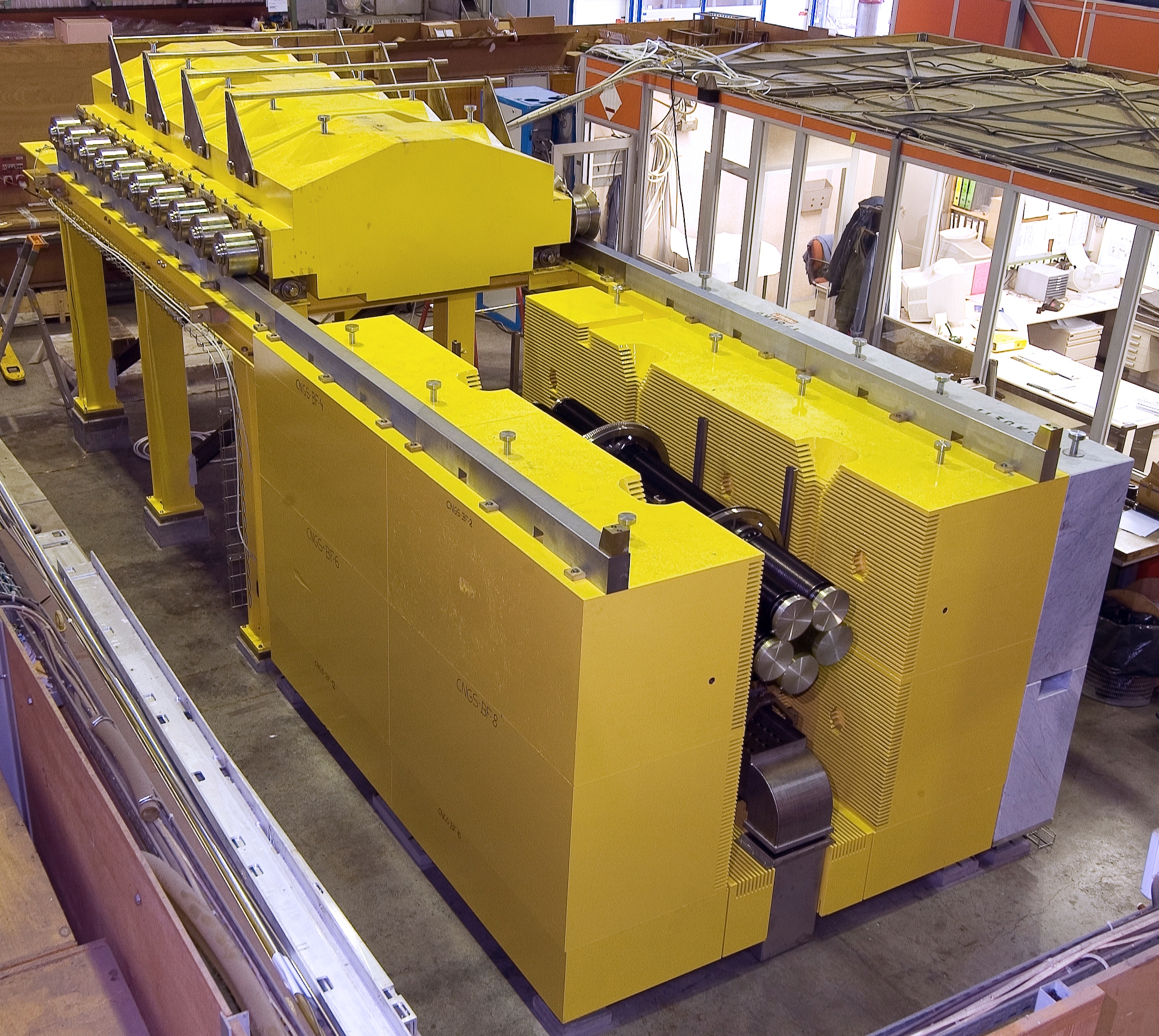
Photos of shielding and
assembled target station |
|
|
|
|
 |
Target
station base- and side-shielding; upstream support frame for roof
shielding, 24 May 2005 |
|
|
|
 |
One of
five roof shielding blocks, 24 May 2005 |
|
|
|
 |
Target
station assembly with roof closed, 8 August 2005 |
|
|
|
 |
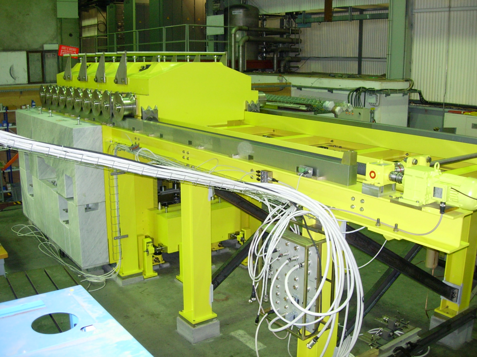
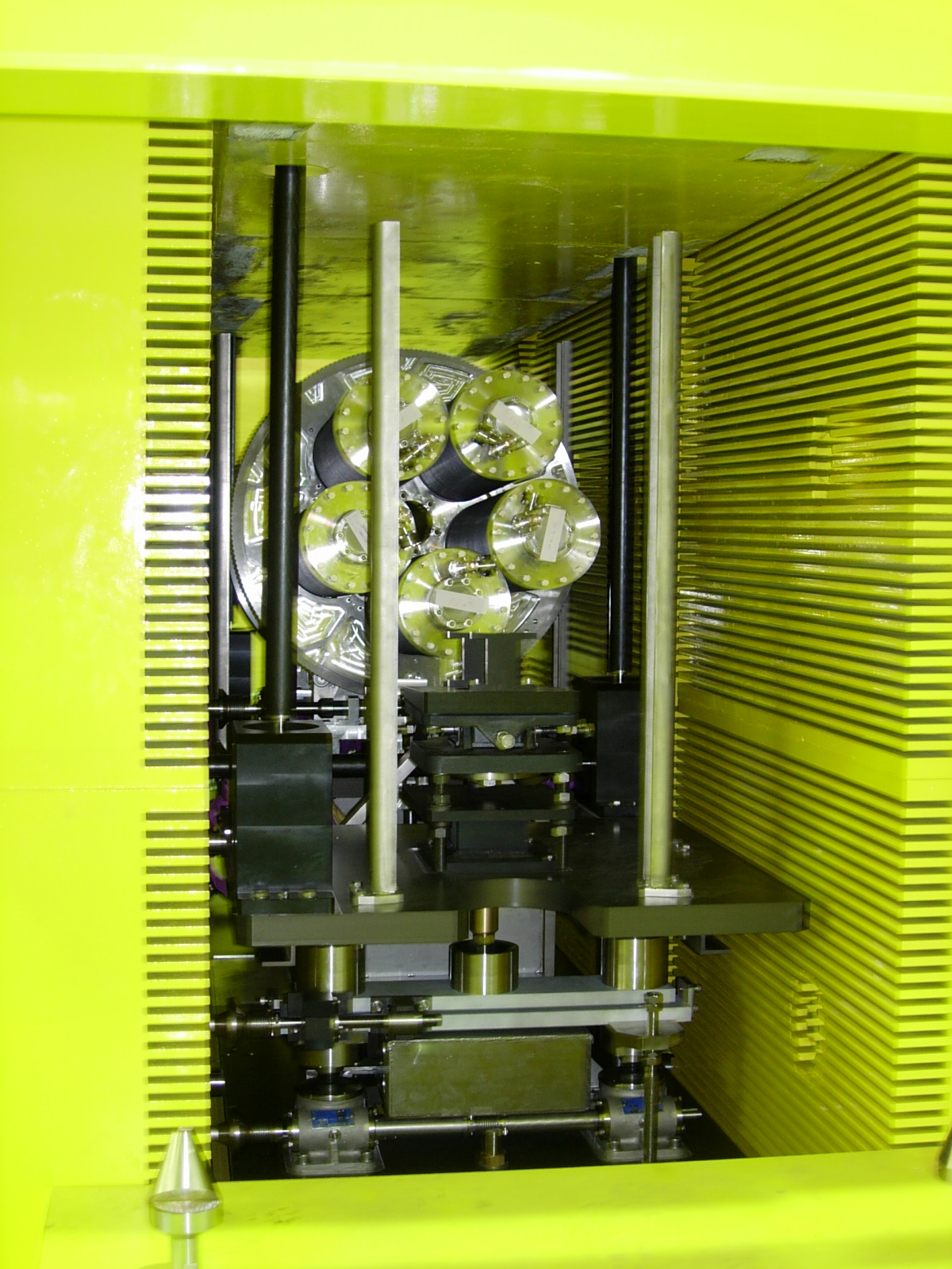
Marble
shielding with the 6 motors installed, 10 August 2005 |
|
|
|
 |
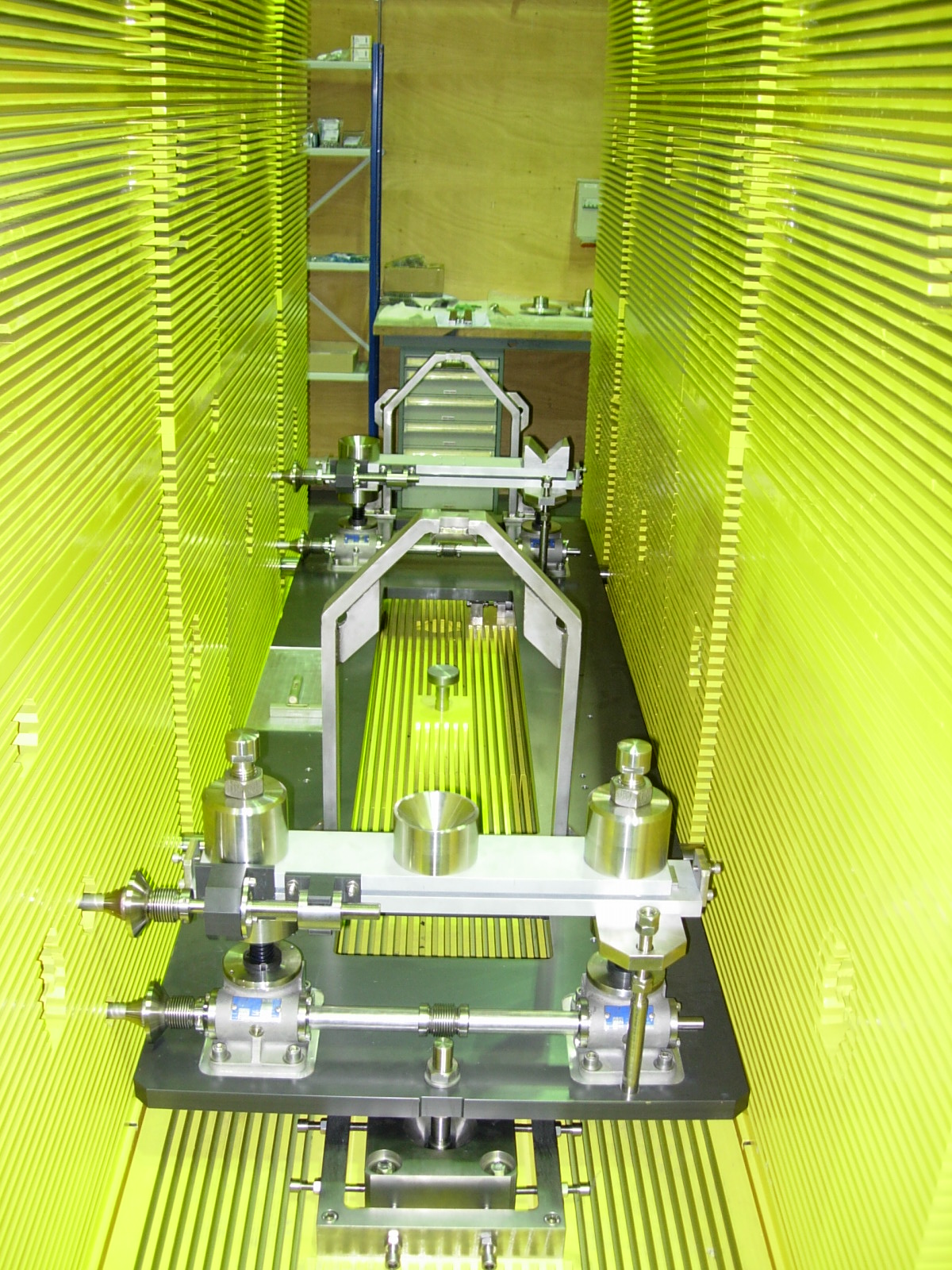
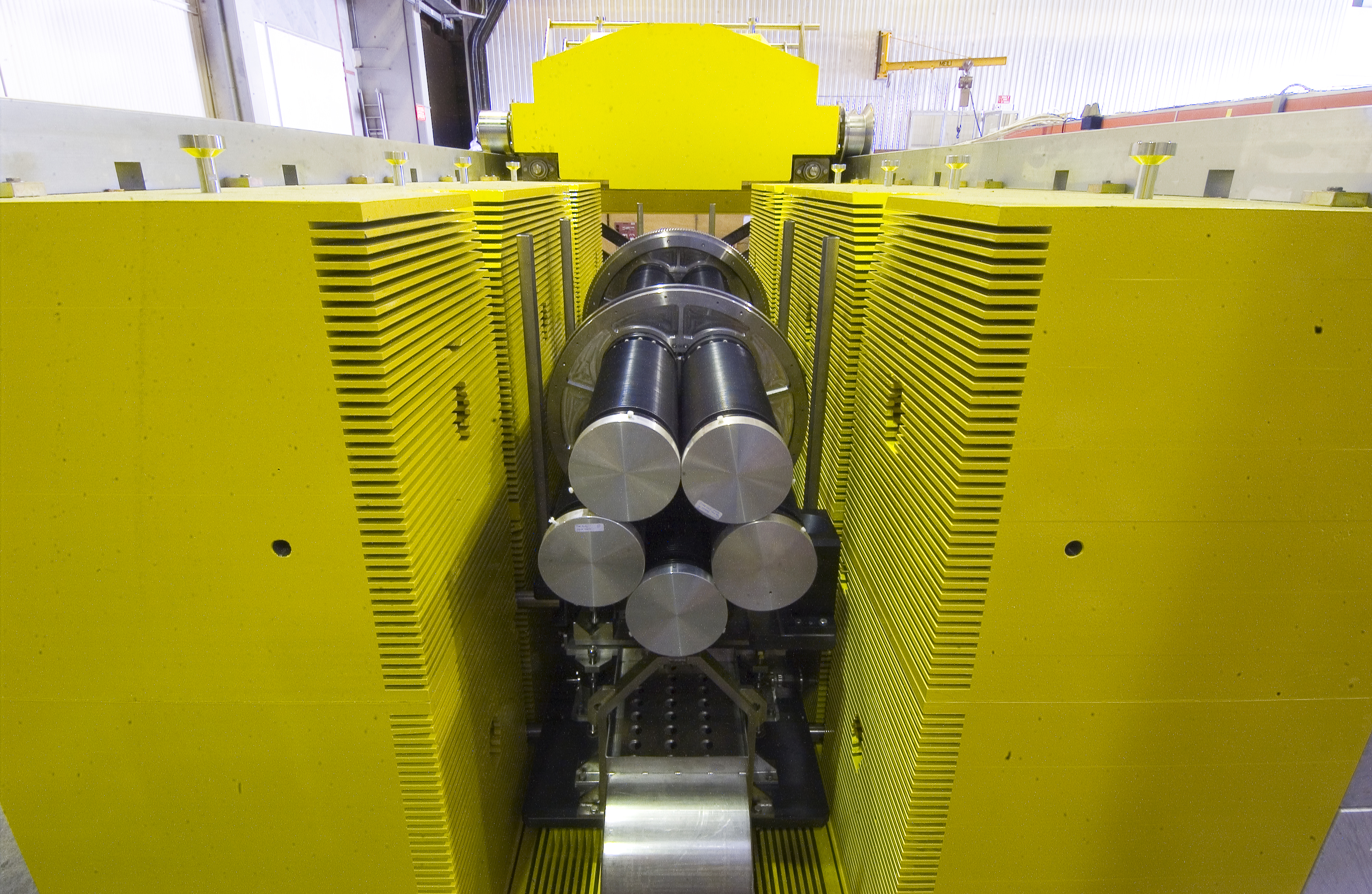
Beam
view of target magazine installed in target shielding, 10 August 2005 |
|
|
|
 |
Target
magazine inserted in target shielding; view against beam direction (12
August 2005) |
|
|
|
 |
Target
station including roof shielding (open), 12 August 2005 |
|
|
|